Loads - Joint Load / Displacement
You may specify joint loads,
and enforced joint displacements and joint
mass in any of the global degrees of freedom. Loads and displacements
may be applied in any non-global direction by defining components of the
load in the global directions. This may be accomplished graphically
or in the spreadsheets. See Drawing Joint Loads below to learn how
to apply joint loads/displacements/masses
graphically.
Drawing Joint Loads
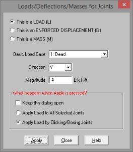
You can apply joint loads to joints. You
must enter the load direction, magnitude and type. Make sure that
you are careful to enter the correct BLC number that you want the loads
assigned to. See Joint Load/Displacement above for more information
on joint loads.
- If
there is not a model view already open then click
 on the RISA Toolbar to open a new view
and click
on the RISA Toolbar to open a new view
and click  to turn on the Drawing
Toolbar if it is not already displayed.
to turn on the Drawing
Toolbar if it is not already displayed.
- Click
the Apply Joint Loads
 button and
define the load. For help on an item, click
button and
define the load. For help on an item, click  and then click the item.
- You
may apply the load by choosing jointson the fly or apply it to a selection
of joints.
To choose joints
on the fly choose Apply by Clicking/Boxing Joints and click/box on the joints with the left mouse button.
To apply the
load to a selection, choose Apply Entries to All Selected Items.
- To apply more loads
with different parameters, press CTRL-D to recall the Joint Loads
settings.
- You may also specify
or edit joint loads/displacements in the Joint Loads Spreadsheet.
- You may undo any
mistakes by clicking the Undo

 button.
Joint Load Spreadsheet
The Joint Load Spreadsheet
records the loads for the joints and may be accessed by selecting Loads
 Joint Loads on the Spreadsheets menu.
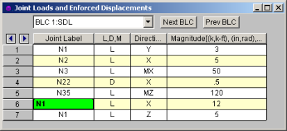
When you open this spreadsheet you
may view only one basic load case at a time. Use the drop down list
on the toolbar to specify a different load case. The current load
case is also displayed in the title bar at the top of the spreadsheet.
The Joint Label specifies the joint
that receives the load or displacement. The same joint may be listed
any number of times.
The next column indicates the value
is a load or an enforced displacement. Enter "L" if it’s
a load, "D" if it's a displacement and
“M” if it is a mass.
The direction code indicates in which
of the global directions the value is applied. Valid entries are
X or Y for the translational directions, or MZ for the rotational direction.
The Magnitude column holds the value of
the load, displacement or mass. The appropriate units for the magnitudes
are displayed at the top of the column. Which units apply depends
upon whether the value is a load, displacement or mass, and whether the
direction is translational or rotational.
- If
you have a “Reaction” or a “Spring” boundary condition for the same degree
of freedom that you have an enforced displacement assigned, NO reaction
will be calculated. See Reactions
at Joints with Enforced Displacements to learn how work around this
limitation.
Joint Mass
For more sophisticated dynamics modeling, you can
enter your mass directly as a mass rather than have the program convert
it from a load. Using joint masses offers several advantages such
as being able to define directional mass and also the ability to specify
mass moment of inertia’s to account for rotational inertial effects.
The units used for Joint Mass are derived from the current Force
and Length units as specified on the Units settings.
For example, if the current force units are Kips and the current length
units are Feet, you will need to specify your mass as kips / g and mass
moments of inertia as kip-ft2
/ g where g is the acceleration of gravity given in those units (feet
per seconds squared).
When specifying a joint mass on the Joint Loads spreadsheet,
enter an “M” for the load type. The directions are defined
relative to the global axes. Enter translational mass using the
global X, Y, or Z codes and mass moments of inertia
by specifying the global MX, MY or MZ.
Joint masses only allow dynamic response in the direction that they’ve
been applied. This can be a very effective way to prevent local
modes. A good example is a floor diaphragm modeled with plate/shell
finite elements. If the mass is only specified for the two lateral
directions, you will prevent any unwanted vertical modes. Care must
be taken in limiting dynamic response using directional mass for complicated
structures. A structure that has “coupled modes” will not give the
“real” dynamic response when mass is only specified in one or two directions.
A coupled mode is a mode that has mass participate in two or three directions
at one time.
Joint masses also allow you to account for rotational inertia effects
by specifying a mass moment of inertia. These are particularly important
when you’re using a rigid diaphragm and you’ve also lumped all your mass
at one point (typically the center of mass). The rotational inertia
effects contribute to the torsion on the diaphragm and should not be neglected.
The following table shows some typical diaphragm shapes and the formulas
to calculate their mass moment of inertias. Note that you can use
the axis transformation equation to calculate the mass moment of inertia
for diaphragms that are combinations of these basic shapes. For
very irregular diaphragms, a more general equation is given based on the
in-plane moment of inertia and the area of the diaphragm.
Mass Moment of Inertia About
an Axis Through the Center of Mass
In the table below C.M. is the center of mass point.
M is the total Mass of the area (typically including self weight, dead
load, and a percentage of the live load) and is assumed to be uniformly
distributed throughout. Ixx is the moment of inertia about the X-X
axis. Izz is the moment of inertia about the Z-Z axis. A is
the area. MMIo is the mass moment of inertia about some other point.
| Area Plan View |
Formula |
|
|
M (b2 + d2) / 12
|
|
|
M d2 / 8
|
|
|
M (Ixx + Izz) / A
|
|
|
MMIo + M D2
|